
Design Guide
Material used : Silicone rubber
Function :Establish contact between the LCD & PCB .
All elastomeric inter-connectors are 'custom made' Zebra connectors offer a wide variety of application possibilities. Unlike other connectors, they do not entail soldering to make reliable connections. They require a minimum of installation hardware considerations, allowing for very small packaging structures to support low profile display and microelectronic interfacing.
When properly dimensioned, long-life performance can be assured and airtight connections without additional precautions can be realized.

PITCH OF INTER-CONNECTOR(P)
- More than three (3) conductive contacts per electrode of PCB/LCD.
- Distance from center-center of each conductor in a connector
- Alternate layers of insulation width (i) & conductor width (c) silicone material evenly spread over the entire length of inter-connector.
- e.g. Pitch (0.1 mm) = i (0.05 mm) + c (0.05 mm)
- Basically, 2 conductors per electrode are often adequate, but 3 conductors per electrode are always recommended to ensure reliable connections and to eliminate "intermittent contact"
- e.g. LCD pitch = 1.2 mm (with contact pad 0.6 mm)
Inter-connector pitch = 0.18 mm is recommended"

| Pitch | Application |
| 0.18 mm [standard] | Simple segment LCD |
| Fine pitch 0.1mm | Dot matrix LCD |
| Very fine pitch 0.05 mm | Graphics LCD |
| Finest pitch 0.03 mm | Graphics LCD in high requirement |
| The number of conductors per inch = pitch | |
| Conductors per inch | Pitch (mm) | Pitch (in inch) |
| 141 | 0.18 | 0.007" |
| 254 | 0.1 | 0.004" |
| 508 | 0.05 | 0.002" |
INTER-CONNECTOR - LENGTH(L)
- L > Length of LCD pads : ±0.2mm or above
- The overall length is recommended to be extended a min. of 0.5mm beyond the edge of the contact at each end of the connector.
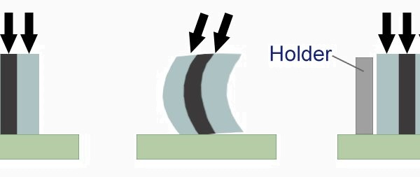
INTER-CONNECTOR - WIDTH(W)
- W ≤ width of LCD ledge.
- Its design is critical in eliminating buckle when clamping force is applied to the connector.
- If the buckle is too severe, contact shall lost completely.
- If connector width is too thin, it may require holder to facilitate assembly, prevent accidental side contact & eliminate alignment problems.
INTER-CONNECTOR - UNCOMPRESSED HEIGHT(H)
- Connector height is determined by the separation distance between LCD & PCB, including tolerance variations.
- It is critical to calculate the correct compression ( deflection rate ) to be applied to the connector for reliable connections.
- Compression ( deflection rate ) to be applied to connectors varies with different types, dimensions of inter-connectors.
- Generally speaking, compression set for inter-connector is ~ 10 - 15%
- Guideline for reference :
- H < 6 mm, ~ 15% compression of connector's height
- 6 mm < H < 10 mm, ~ 13% compression of connector's height
- ≥10 mm, ~ 10% compression of connector's height
- X = n / 1 - p Formula to determine the uncompressed height of the connector
- x = uncompressed height
- n = compressed height (= separation distance between LCD & PCB)
- p = percent of desired compression
- Compression load should be spread evenly over the top surface of the inter-connectors.
- To avoid bending, we recommend to use holders especially for tall height inter-connector.
- Holder should give space for horizontal expansion of the inter-connector during compression.

CONDUCTIVE CORE WIDTH(YL)
- Conductive width is important in determining the cost, resistance and hardness of the connector.
- For connector width > 1.3 mm, the more conductive material a connector contains, the more expensive it is.
- Standard core width = 0.6 mm

APPLICATIONS

DESIGN GUIDE

- Pitch (P): More than three (3) conductive contacts per electrode of PCB/LCD
- Length (L) : + 2mm or above
- Uncompressed Height (H) : Distance between LCD & PCB +10-15% compression rate
- Width (W) : determined by the width of LCD ledge
SPECIFICATION
