導電性シリコーン・ゼブラ・エラストマー・コネクタ
YF /カスタム(L字型/ F型)コネクタ
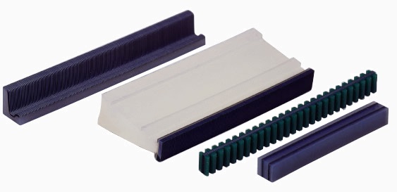
YF型
YF型は主にグラフィックスLCDに使用され、共通側の上面にコンタクトパッドがあります。YF型の最大の利点は、他の従来のインターコネクターと比較してLCDの上部がPCBに直接接続できることです。
すべてのYF /カスタムコネクタは特別に設計されたツールを使用してオーダーメイドで調整されます。

適用例
グラフィックスLCDの一般的なパターン

寸法

公差
| (単位: mm) | ||||
| 0.05P | 0.1P | 0.18P | ||
| P | 勾配 | 0.05 ± 0.025 | 0.1 ± 0.03 | 0.18 ±0.04 |
| L | 長さ | L ≤ 10 ±0.3 10≤L ≤ 70 ±0.4 70 < L ≤ 120 ± 0.6 120 < L ≤ 200 ± 1.0 200 < L ≤ 300 ± 1.5 |
||
| H | 高さ | 4.5<H≤7.0 ± 0.4 7.0<H≤10.0 ± 0.6 | ||
| H1 | ± 0.15 | |||
| H2 | 2.0<H2≤5.0 ± 0.4 5.0<H2≤8.0 ± 0.6 | |||
| W | 幅 | 3.5<W≤4.5 ± 0.2 4.5<W≤6.5 ± 0.4 | ||
| Wa | ± 0.1 | |||
| W1 | ± 1.0 | |||
| W2 | ± 1.0 W2 = W - W1 - Wa | |||
| W3 | ± 1.0 | |||
| W4 | 1.0 ± 0.7 | |||
| D | LCDパネルとの接続距離 | ± 0.2 | ||
圧縮曲線

カスタム型(L型/ F型)
当社では、お客様のデザインごとに、導電性のシリコンインターコネクタsdを開発します。その場合には、特に次のような場合に、適切な型のインターコネクタをお勧めいたしますので、LCDモジュールを設計する前に当社のR&Dエンジニアにご相談ください。
(1) LCDとPCBが非平行の場合。
(2) 他の部品の制約のためにLCDモジュールを設計することが困難な場合。
(3) 3本以上の導線が必要な場合。